
By the time a new cooling structure shows up in a vendor briefing, several numbers in your design are already frozen.
Chassis height went into the mechanical envelope months ago. Fan part numbers went into the BOM. The rack power allocation went into a conversation that is not easy to reopen. If a liquid loop is in the plan, committing tooling for cold plates sits on a schedule that runs ahead of silicon.
So the useful question about a new air-cooling structure is not whether air cooling is making a comeback. It is narrower: does this change any of the numbers I am about to sign off on?
Answering that means knowing which part of the heat path the structure touches, and whether that part is the one currently limiting the system in front of you. Those are two different questions, and vendor material rarely separates them.
Table of Contents
ToggleWhat Does a 3D Vapor Chamber Actually Improve?
A 3D vapor chamber lowers heat-spreading and two-phase transport resistance, the middle segments of the path from chip to air. Whether that moves an air-cooling limit depends on which segment dominates in the specific system, and on two budgets outside the thermal path entirely: vertical space and fan power.
Direct answer
A 3D vapor chamber is a structural category, not a product line: the cylindrical extensions and the plate enclose a single, shared vapor space. What it improves is heat spreading and two-phase transport — the middle of the path from chip to air.
Whether that moves your air-cooling limit depends on which part of that path currently dominates, and on two budgets that appear nowhere in it: vertical space and fan power.
One thing worth knowing before comparing anything: the terms on both sides of the air-versus-liquid line are used inconsistently across sources.
What "3DVC" Refers To—and What It Doesn't
Start with what the term denotes, because the most common description of it is wrong in a way that matters.
A 3D vapor chamber is not a vapor chamber with heat pipes bonded onto it. The defining feature is that the cylindrical sections rising from the plate and the plate itself enclose a single, shared vapor space. Vapor generated over the heat source moves into the vertical sections without crossing a soldered or thermally-pasted interface, and condensate returns through wick structures continuous with the plate. The distinction is not pedantry: the bonded version carries an extra thermal joint that the shared-cavity version simply does not have, and removing that joint is part of what the structure exists to do. Describing it the wrong way hides one of the things it actually improves.
That is how the term is used among module suppliers building for high-power server and networking equipment. There is no standards-body definition — which is the first hint of the problem this article is about. The same three-letter label also appears on desktop CPU coolers rated for a few hundred watts, alongside server modules built for kilowatt-class accelerators.
The word on the other side of the boundary is looser still.
Ask three sources what “direct liquid cooling” covers and you get three boundaries. Uptime Institute counts six DLC categories — three cold-plate variants and three immersion variants — and explicitly excludes rear-door heat exchangers, because those still rely on air to carry heat out of the IT equipment. A major server OEM’s whitepaper draws the line differently: “liquid cooling” is the umbrella covering rear-door exchangers, cold plates and immersion, while “DLC” is reserved for bringing coolant directly to the heat source — in its own servers, cold plates. Common vendor usage narrows it further, treating immersion as a separate category to be compared against DLC rather than a type of it. One boundary puts immersion inside; another puts it outside.
So the same term denotes different scopes in different documents — and the scope difference has engineering consequences, which come back into play when the fan budget does.
Five Segments, One Path
Any comparison between cooling structures needs a shared instrument. This one breaks the path from junction to ambient into five segments:
- Die and package to the spreader — die-attach stack, lid, interface material.
- Spreader into the heat pipe or vapor chamber.
- Internal spreading and two-phase transport.
- Fin surface to moving air.
- Chassis and rack-level heat rejection.
The fifth segment is the one a cooler vendor cannot characterize at all: it depends on what the device gets installed in.
A 3DVC acts on segments 2 and 3 — the handoff into the two-phase device, and the transport inside it. Both are genuine improvements. Neither touches segments 1, 4, or 5.
One question belongs here, right after segment 3. Vacuum integrity and the removal of non-condensable gases determine yield in two-phase devices; insufficient evacuation leaves residual gas behind, which surfaces as a failed thermal test. More complex internal geometry makes both harder. So the useful question about any new two-phase geometry is not whether a sample performs well. It is whether the samples that performed well came out of a process that repeats at volume.
Where a 3DVC Acts—and What That Does to the Total
Resistances in series add, and that arithmetic decides whether an improvement to spreading and transport is visible at the junction.
Pick an allocation — any allocation. Suppose:
- fin-to-air (segment 4): 70% of total resistance
- spreading and transport (segments 2 and 3): 20%
- die and package (segment 1): 10%
Now halve segments 2 and 3. In this illustration twenty becomes ten, the total falls from 100 to 90, and resistance from junction to ambient is 10% lower.
Those numbers are illustrative, not typical values. There is no defensible “typical” split — published figures scatter widely, and yours depends on your package, interface, fin geometry and airflow. That is the point, not a caveat: the arithmetic holds for any allocation you substitute. An improvement to a minority segment gets diluted in proportion to how small its share was to begin with.
This is an argument about proportions, not a method for predicting a junction temperature. Datasheet resistances are measured under conditions that differ from your installation, and adding them will not produce a number you can act on.
Which means the same 3DVC can be a substantial gain in one system and close to a rounding error in another, with no change to the device itself.
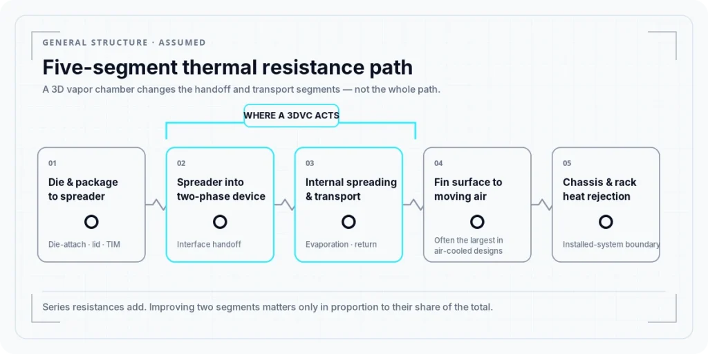
Caption: A 3DVC changes two of five segments in series. Whether that is decisive depends on which segment is largest in your system.
Why It Needs Height, Not Length
A 3DVC needs vertical room. The reason is frequently stated backwards, and the backwards version is worth correcting directly.
The vertical extensions are not there because a longer path carries heat better. Lengthening a two-phase device does not raise its transport ceiling: the capillary limit — how much power the wick can keep returning liquid against — falls roughly in inverse proportion to effective length, at a given orientation and working fluid.
The height is there because height is where fin area comes from.
A taller structure supports a taller fin stack, and fin area is what segment 4 — fin-to-air — is made of. The transport section carries heat up into that fin volume. Remove the height and the fin stack shrinks; without the fin stack, the resistance removed from spreading and transport has nowhere to go. So the vertical space is a trade, not a free upgrade: you spend enclosure height to buy fin area, and the transport section you lengthened to reach it is marginally worse at transporting than a shorter one would be. The trade is usually worth making. It is still a trade.
So the same structure that helps in a 4U chassis can be uninteresting in 1U — and that is why the 1U question is worth asking at all. In this class, rack density is a first-order objective, so vertical space is conserved wherever it can be. Height is not a spare resource. It is one of the things the design is actively trying not to spend.
Two Budgets That Aren't on the Thermal Path
Segments 1 through 5 tell you whether the heat can get out. They say nothing about what getting it out costs. Two costs matter here, and neither appears anywhere in the five segments.
The Volume Budget: What a Generation Boundary Looks Like
Vertical space is a budget, and at the current generation boundary it is being spent visibly.
Take one system integrator’s eight-accelerator platform. Same generation, same eight devices: the liquid-cooled chassis is 4U, and the air-cooled version is 8U to 10U. The liquid-cooled form factor carried over unchanged from the previous generation. The air-cooled one needed a redesigned chassis to open up thermal headroom for eight devices in the 1,000 W class. Air-cooled designs in this class have commonly relied on shared-vapor-space structures, though published adoption shares are not available.
In that platform’s case, air cooling did not disappear at the boundary. It roughly doubled in height — spending the one resource the previous section described as the thing designs are built to conserve.
The Power Budget: Fan Power Rises With the Cube of Speed
The second budget is electrical, and it is often left out of thermal discussions entirely.
Fans consume power, and the scaling is unforgiving. Along a given system resistance curve, airflow rises in proportion to fan speed, static pressure with the square of speed, and shaft power with the cube of speed. Twenty percent more speed costs roughly 73 percent more power. Doubling speed costs eight times the power.
Magnitudes are worth having in hand. Distributor listings for the 40 × 56 mm dual-rotor fans used in 1U servers put rated maxima somewhere in the 13 to 25 W range. Multiply that by the number of fans in your own 1U node. Those are rated maxima rather than operating values — actual draw follows whatever PWM duty the controller happens to be commanding. Even so, a fan bank at high duty is a non-trivial share of node power, none of it producing compute.
One objection deserves a direct answer, because it is the correct objection.
If a 3DVC lowers spreading and transport resistance, shouldn’t the same heat leave at lower airflow — saving fan power along the way? Yes, but only when those are the dominant resistance. If the largest segment is already fin-to-air, reducing spreading and transport barely changes the airflow required, and the fan power stays where it was. The arithmetic from earlier applies here as well.
Which is where the terminology problem returns. If the liquid path in the plan is cold-plate DLC, coolant reaches the components that have cold plates on them; whatever heat is not on a cold plate still leaves the chassis in moving air. The fan budget does not vanish at the transition. One vendor’s own specification for its cold-plate system claims capture of most component heat — CPU, GPU, PCIe switch, DIMM, VRM, PSU — but not all of it.
When Acoustics Become the Practical Limit
There is a further constraint: in products with an acoustic requirement, noise can limit usable fan speed before the fan reaches its electrical or mechanical limit.
Fan power is not the only cost of increasing airflow. In products with an acoustic specification, higher fan speed may become unacceptable before the fan reaches its electrical or mechanical limit. This is especially relevant in workstations, edge systems, telecom equipment, and other environments where noise is part of the product requirement.
The point is not that acoustics always dominate. It is that airflow is constrained by more than thermal capacity alone. A cooling structure can reduce resistance elsewhere in the thermal path and still leave the system bounded by airflow, noise, space, or power.
The difference between those two ceilings is not simply which number is larger. In some products, the acoustic limit is enforced as an explicit operating requirement, such as a maximum allowable fan speed or sound level. In some systems with an acoustic specification, that requirement is implemented as a fan-speed limit. Published control implementations also show workload power capping as a fallback when additional cooling demand cannot be met within that limit. In such implementations, additional thermal demand may therefore be handled by limiting workload rather than allowing fan speed to increase further.
That changes the usual framing. “Just spin them faster” may be blocked not by the fan’s electrical limit, but by an acoustic requirement—and in those cases, the cost appears as reduced performance rather than additional fan power.
The practical consequence for evaluating a new structure: a claim measured at a fan speed the product cannot use is not a claim about that product. Test-condition airflow and the acoustic envelope of the target system are the same question asked twice.
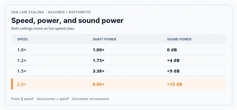
Caption: Fan speed raises both power demand and sound level. Which one becomes the practical limit depends on the product requirements.
Reading a New Air-Cooling Claim
None of this settles whether a 3DVC is worth adopting. It leaves three questions that have to be answered before that can be settled.
Which segment does it change? Structural claims are usually specific and checkable. A shared vapor space acts on spreading and transport. A different fin geometry acts on fin-to-air. A different interface material acts on the package. Ask which one — and treat material that answers with a temperature delta instead as not yet having answered.
Is that segment dominant in your stack? This is the question that decides the answer, and it cannot be answered from the vendor’s data at all. It depends on the package, mounting, fin volume, and airflow of the system being designed.
Do the published test conditions represent that system? Power, heat-source area and the other conditions a wattage number leaves out, mounting method, airflow, acoustic limit, dimensional envelope. A number produced under conditions that cannot be reproduced is not transferable, however carefully it was measured.
None of this makes liquid cooling the better technology, or air cooling the obsolete one. They are different operating regimes with different binding constraints. Change the constraints and the answer changes — which is not a statement about which one is more advanced.
That returns the original question to a shape it can be answered in. A structure that lowers spreading and transport resistance extends the range over which an air-cooled design stays viable. It redefines the limit only for systems where spreading and transport were the limit. Everywhere else it improves a number that was not the binding one — which is worth having, but it is not the same thing.
Key Takeaways
- A 3DVC acts on the spreading and transport segments, not on fin-to-air or on chassis-level rejection.
- Series resistances dilute a minority-segment improvement in proportion to its share.
- Vertical space and fan power are budgets that sit outside the thermal path.
- In products with an acoustic requirement, acoustics can become a practical airflow constraint before the fan reaches its electrical limit.
- “Direct liquid cooling” is defined differently across sources, and the difference changes what the fans still have to do.
Where Published Claims Stop
Hyper Cool Lab does not draw cooling-architecture conclusions from published claims. Vendor data, application notes, and simulation are inputs and hypotheses — useful for framing a comparison, insufficient on their own for a decision that precedes tooling, first silicon, or a customer commitment. What changes a decision of that kind is comparable evidence: a controlled baseline, stated conditions, and a record of what was and was not tested.
For the historical framing behind why the thermal bottleneck keeps relocating, see Whose Limit Is the Air-Cooling Limit?.
Common Questions
Is a 3DVC the same as a vapor chamber with heat pipes attached to it?
No. In a 3D vapor chamber the cylindrical sections and the plate enclose a single, shared vapor space. A bonded assembly carries an extra thermal joint that the shared-cavity version does not have. The term has no standards-body definition, and it is applied to products spanning a wide power range.
Does lowering thermal resistance with a 3DVC reduce fan power?
Only when spreading and transport are the dominant resistance in that system. If fin-to-air is already the largest segment, reducing the others barely changes the airflow required, and fan power stays where it was.
Does direct liquid cooling remove the need for server fans?
It depends on what “direct liquid cooling” means in the document you are reading, because sources draw the boundary differently. Where it means cold plates, coolant reaches the components that have cold plates on them; heat that is not on a cold plate still leaves the chassis in moving air.
References
- Uptime Institute — Direct liquid cooling: pressure is rising but constraints remain. Six DLC categories; rear-door heat exchangers excluded. journal.uptimeinstitute.com
- Server OEM whitepaper — Deep Dive into Direct Liquid Cooling. “Liquid cooling” as umbrella term; DLC as coolant brought directly to the heat source. delltechnologies.com
- Industry analysis — datacenter cooling systems overview, on how rear-door exchangers are labeled. newsletter.semianalysis.com
- Managing Cooling Fan Noise In Product Design, Electronics Cooling — A-weighted sound power level and the 50 log(RPM) speed term. electronics-cooling.com
- Server acoustics and fan-law scaling — sound power with the fifth power of rotational speed. upsite.com
- US 11350543 — acoustic limits in thermal control: acoustic-based fan speed limits with workload power capping as fallback.
- US 10061332 — cooling fan speed increased up to, but not beyond, the maximum sound level specification.
- System integrator product and release documentation — 4U liquid-cooled and 8U/10U air-cooled eight-accelerator platforms; 1,000 W-class device TDP.
- Distributor-listed specifications for 40 × 56 mm dual-rotor server fans — rated maxima 14.8 W, 21.8 W, 22.8 W.
- Module supplier technical pages — shared-cavity 3D vapor chamber construction and two manufacturing routes.