
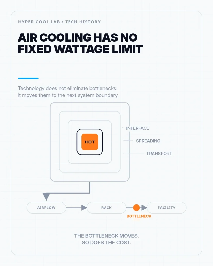
“Air cooling has reached its limit.”
Engineers have repeated some version of that sentence for decades. Sometimes it has been directionally correct. It has rarely been complete.
The missing question is:
Which limit?
Is the limit at the package interface? Is heat failing to spread across the cooler base? Has a heat pipe reached its transport boundary? Are the fins receiving enough heat while the fan can no longer push more air through the chassis at an acceptable power or acoustic cost? Can an individual server still be cooled while the rack or room can no longer reject the accumulated heat?
A thermal system does not have one boundary. It has a chain of them.
That is why cooling history is not a clean sequence in which a superior technology replaces an inferior one. Heat pipes did not make solid heat sinks obsolete. Vapor chambers did not replace every heat pipe. Liquid-to-air cooling did not become technically invalid when direct liquid cooling gained importance.
Each technology addressed a particular constraint. Once that constraint moved, the next part of the system became visible.
Cooling technologies do not eliminate limits. They move the dominant bottleneck—and change which part of the system must absorb the cost.
Table of Contents
ToggleIn Brief: Air Cooling Has No Single Limit
Air cooling has no universal wattage limit independent of system conditions. The practical limit may lie in the package, interface, heat spreading, heat transport, fin-to-air convection, fan power, acoustics, chassis airflow, rack heat rejection, serviceability, or infrastructure. The active bottleneck must be identified before a more complex cooling architecture is justified.
Air Cooling Does Not Have One Boundary
Before asking how many watts air cooling can handle, it helps to separate four functions that are often grouped under the single word “cooling.”
First, heat must be spread from a concentrated die, package, or hotspot over a larger usable area.
Then it must be transported to a place where a heat exchanger can work effectively.
Next, it must cross from a solid surface into a moving fluid through convection.
Finally, it must be rejected from the complete system—out of the server, rack, room, or building.
In simpler terms:
Spread the heat, move it, hand it to a fluid, and then remove it from the environment that must stay operational.
A design can perform well in one layer and fail in another.
A vapor chamber may distribute heat effectively across a base while the fin stack remains too small. A large fin stack may have adequate area while the chassis cannot deliver enough pressure or airflow. A cold plate may collect heat effectively from a GPU while a server-internal radiator must still release the same heat into room air.
The same pattern repeats throughout cooling history:
- A dominant bottleneck becomes too expensive or impractical.
- A technology reduces or moves that bottleneck.
- The next constraint becomes more important.
- The system must decide whether moving it again is worth the cost.
The result is not a universal wattage ladder. It is a moving boundary.
Heat Pipes Moved the Limit from the Base to the Fins and Airflow
A conventional metal heat sink depends on conduction through its base and fins. As heat sources became smaller and cooler geometries larger, remote fin area could remain thermally underused.
The problem was not always a lack of fin area.
The problem was getting heat to that area.
The modern capillary heat pipe was formalized in the early 1960s. George Grover’s 1963 patent described an evaporation–condensation device that used vapor transport and capillary return to move substantial heat with a relatively small temperature drop. The patent documented several container-and-fluid combinations, including stainless steel and sodium experimental devices.[1]
In a conventional wicked heat pipe, fluid evaporates at the hot region, vapor moves toward a cooler condenser, and the condensate returns through capillary action. For electronics cooling, this connects a compact heat source to a larger or remotely positioned fin field.
The working fluid and container, however, are not universal.
Early Grover work included high-temperature liquid-metal systems. Spacecraft thermal-control systems have often used aluminum–ammonia designs. NASA also documented copper flat-plate heat pipes using methanol, while copper–water heat pipes became common in electronics on Earth and aircraft before later receiving relevant spacecraft flight testing.[2][3]
These are different application and temperature-range choices—not one fluid replacing another in a single historical sequence.
The functional lesson is simpler than the history:
A heat pipe does not reject heat.
It moves heat from one location to another.
Once heat can reach the full fin field, the next limit may appear in fin efficiency, airflow resistance, fan pressure, inlet temperature, fan power, or noise.
A better transport device can therefore make the air-side bottleneck more visible.
The cooler has improved, but the system has not escaped air.
Vapor Chambers Moved the Limit Across the Base
Heat pipes are often associated with moving heat along a preferred direction. A vapor chamber addresses a related but different problem: distributing concentrated heat across a broader area.
A small die or package may inject heat into a much larger base. Even when the cooler has enough surface area, conduction through the base can create a spreading penalty before heat reaches it.
A vapor chamber can be understood as a flat, two-dimensional heat-pipe structure: vapor spreads through a planar volume, condenses over cooler regions, and returns through a capillary structure.
NASA records from 1975 describe copper flat-plate—or vapor-chamber—heat pipes using methanol and internal capillary grooves. Two panels were also tested during a sounding-rocket flight.[3]
That experiment is not the origin of every modern electronics vapor chamber. It does show that the flat-plate two-phase concept predates today’s high-power processors.
In an electronics cooler, the bottleneck is easier to understand in functional terms:
- The heat source is concentrated.
- The cooler base is larger.
- Pure conduction creates a spreading penalty.
- The vapor chamber distributes heat across more of the usable area.
This can reduce the temperature penalty between the source and the downstream transport or fin structure.
It does not guarantee that the complete system has enough cooling capacity.
If the air-side heat exchanger, fan system, chassis intake, or exhaust path is already constrained, improving base spreading may produce only a limited system-level benefit.
The vapor chamber may have completed its task while the server remains thermally limited.
Better spreading does not remove the need for transport, convection, and final heat rejection.
It moves the argument downstream.
Thermosyphons Show Why Valid Technologies Can Remain Niche
A two-phase thermosyphon uses boiling, condensation, gravity, and density differences to circulate a working fluid without a mechanical pump.
The approach can reduce moving parts and pumping power, but it is integration-sensitive. Height difference, orientation, condenser location, startup behavior, refrigerant charge, and chassis packaging all matter.
Commercial thermosyphon products have been developed for CPU, GPU, and 1U server applications.[4] That proves that the architecture entered real server use; it does not prove broad adoption across the server market.
This makes the thermosyphon a useful counterexample to a simplistic technology history.
A technology can work, reach commercial systems, and remain valuable without becoming the dominant architecture.
Technical validity and broad adoption are different questions.
Liquid Entered the Server, but the Heat Still Returned to Air
By the beginning of the 2020s, high-power server cooling was increasingly a system problem rather than only a component problem.
A processor cooler could include a vapor chamber or heat pipes and still face excessive fan speed, acoustic output, chassis pressure drop, or exhaust temperature. The package-to-cooler path could improve while the available air budget became increasingly expensive.
From the perspective I encountered among high-power processor and accelerator IC companies, the starting point was not a fixed power number that cooling engineers were simply expected to accommodate.
As long as the complete platform could deliver the required electrical power, remove the resulting heat, and maintain reliable operation, there was a strong incentive to expose more performance—and therefore accept a higher sustained power envelope.
When the platform could not support that target, the practical specification had to fit within the available system boundary. That could mean reducing sustained power, sustained performance, or another deliverable operating condition.
Cooling capability therefore did more than react to processor power. Together with power delivery, packaging, efficiency, reliability, and platform design, it helped determine how much of the silicon’s potential could become a shippable system specification.
Public power-management documentation provides only partial context for this observation. AMD states that EPYC processors operate within limits imposed by the processor, surrounding server infrastructure, and configured parameters; NVIDIA specifies H100 SXM at up to 700 W configurable TDP.[5][6] These sources support the narrower point that the usable power envelope is not independent of the platform. They do not establish one universal IC-company roadmap rule.
The direction toward liquid heat collection was therefore not especially mysterious.
The harder question was who would absorb the transition cost.
The industry effectively had to pay twice.
Inside the server, the transition could require cold plates, tubing, pumps, quick disconnects, controls, leak management, validation, and new service procedures.
At the facility level, it could require rack manifolds, coolant distribution units, building-side loops, monitoring, training, and new deployment practices.
For systems still expected to operate in conventional air-cooled data centers, changing both layers at once was difficult to justify.
This created space for liquid-to-air cooling.
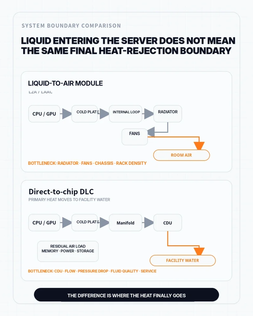
In a server-internal liquid-to-air architecture, a cold plate collects heat from a processor or accelerator. A closed liquid loop transports that heat to an internal radiator or liquid-to-air heat exchanger. Server fans then move air through the exchanger and return the heat to the room.
Liquid solves the local collection and transport problem.
Air still performs final rejection.
The bridge ends in air.
A Public Timeline of the Transition
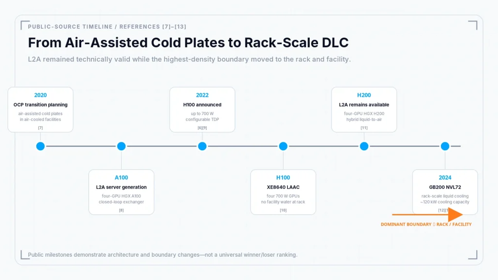
2020–2024: Maturity and a Market Shift
Swipe horizontally to view the full table.
| Time | Public signal | How the bottleneck moved |
|---|---|---|
| 2020 | OCP discussed air-assisted liquid-cooling cold plates for existing air-cooled facilities. [7] | Liquid entered the server while compatibility with the existing facility remained the priority. |
| A100 generation | Lenovo documented a four-GPU HGX A100 configuration using liquid-to-air cooling. [8] | The cold plate handled the GPU load, but final heat rejection still returned to room air. |
| 2022 | NVIDIA H100 SXM was specified at up to 700 W configurable TDP. [6][9] | Accelerator heat load moved closer to the server airflow and density boundary. |
| H100 generation | Dell XE8640 used LAAC for four 700 W H100 GPUs without facility water at the rack. [10] | Liquid-to-air remained technically capable, but used chassis volume and fan capacity to preserve compatibility. |
| 2024 onward | GB200 NVL72 adopted rack-scale liquid cooling with approximately 120 kW of required rack cooling capacity. [12][13] | The dominant question moved from one server to rack density and facility infrastructure. |
| Milestone | What it demonstrates |
|---|---|
| 2020 — OCP transition planning | The Open Compute Project’s Advanced Cooling Solutions track included a session on enabling air-assisted liquid-cooling cold plates in air-cooled facilities.[7] |
| A100 server generation — L2A without facility plumbing | Lenovo documented a four-GPU NVIDIA HGX A100 configuration using a closed-loop Neptune liquid-to-air heat exchanger.[8] |
| 2022 — H100 announced | NVIDIA announced Hopper and the H100; H100 SXM is specified at up to 700 W configurable TDP.[6][9] |
| H100 server generation — Four 700 W GPUs with LAAC | Dell’s PowerEdge XE8640 uses Liquid Assisted Air Cooling for four 700 W H100 GPUs, keeps the CPUs air cooled, and does not require facility water at the rack.[10] |
| H200 server generation — L2A remains available | Lenovo documents an HGX H200 four-GPU configuration with Neptune hybrid liquid-to-air cooling.[11] |
| 2024 — Rack-scale liquid cooling | NVIDIA introduced the liquid-cooled GB200 NVL72. Its OCP design material describes approximately 120 kW of required rack cooling capacity.[12][13] |
The timeline matters because it disproves a simple failure narrative.
Liquid-to-air cooling did not fail because it could not cool high-power accelerators. Public systems show that it could—and still can—support substantial GPU loads.
Its scaling limit appears elsewhere.
Every watt collected by the cold plate still reaches the internal radiator. The radiator still requires area. Fans still require pressure and electrical power. The heated air still leaves the server, enters the room, and must be processed by the facility cooling system.
As accelerator density rises, a liquid-to-air server may remain technically capable while consuming increasing chassis volume, airflow, fan power, and room-level heat-rejection capacity.
That is not a cold-plate failure.
It is a system-scaling boundary.
AI Changed Which Cost Looked More Expensive
The architecture matured just as the market it had been designed to bridge began to change.
It would be inaccurate to say that the AI infrastructure market stopped caring about cost.
What changed was the comparison.
One reasonable engineering interpretation is that, before high-density accelerator deployment became commercially urgent, changing server and facility infrastructure could appear more expensive than accepting lower density.
As demand accelerated, unavailable compute capacity, delayed deployment, lower rack density, and constrained cluster scaling became more expensive outcomes.
The question shifted from:
Why should the facility be modified?
to:
What is the cost if the facility cannot support the required compute density?
This is an interpretation of the system transition, not a claim that every data-center operator followed the same financial decision process.
Liquid-to-air cooling did not become invalid.
Its market role changed.
It remained relevant where facility water was unavailable, infrastructure change was constrained, density targets were lower, or phased adoption mattered more than maximum rack-level capacity.
But in the highest-density AI systems, the center of the problem moved beyond the server radiator.
The dominant bottleneck moved to the rack and facility.
AUTHOR OBSERVATION
The architecture matured just as the market it had been designed to bridge began to change.
Liquid-to-air did not lose technical validity. Its role changed as the highest-density constraint moved beyond the server radiator.
Direct Liquid Cooling Moved the Boundary to the Rack and Facility
In this article, DLC means direct liquid cooling, not diamond-like carbon.
Direct liquid cooling places liquid-cooled interfaces close to the main heat-generating components and connects them to a broader coolant-distribution system.
The important system change is not merely that liquid touches a cold plate.
It is that the primary heat load can move beyond the server without first being returned to room air.
At rack scale, server manifolds may connect through a coolant distribution unit, or CDU, to a facility-side loop. The CDU controls or exchanges heat between the IT liquid loop and the facility system.
This creates a different density and heat-rejection budget.
NVIDIA’s GB200 NVL72 connects 36 Grace CPUs and 72 Blackwell GPUs in a rack-scale, liquid-cooled design. NVIDIA’s contributed design describes approximately 120 kW of required rack cooling capacity and includes liquid manifolds and blind-mate liquid connections as core rack elements.[12][13]
At that scale, the question is no longer whether a better heat sink fits one component. Cooling has become part of the rack, service strategy, fluid-distribution system, and building interface.
Direct liquid cooling does not defeat air cooling.
It reallocates responsibility.
Even a rack-scale liquid-cooled system may remain hybrid. NVIDIA’s GB200 system documentation identifies the Grace CPUs, Blackwell GPUs, and selected networking and switch ASICs as liquid cooled, while the remaining tray components are air cooled.[14]
New constraints appear:
- coolant flow and pressure-drop budgets;
- fluid quality and contamination control;
- material compatibility;
- quick-disconnect reliability;
- leak detection and containment;
- pump and control redundancy;
- serviceability and component replacement;
- rack and facility readiness;
- responsibility boundaries between server, rack, and building operators.
These are not arguments against direct liquid cooling.
They are reasons not to describe it as a universal or cost-free endpoint.
A new architecture changes which team owns the risk.
Cooling Technologies Do Not Form a Replacement Ladder
Swipe horizontally to view the full table.
| Technology | Primary constraint reduced | Constraint not removed | Where the bottleneck moves |
|---|---|---|---|
| Heat pipe | Long-distance heat transport inside a cooler | Air-side heat-rejection capacity | Fins, airflow, pressure drop, and acoustics |
| Vapor chamber | Planar spreading from a small source into a larger base | Overall airflow and chassis capacity | Transport devices, fins, and the air path |
| Thermosyphon | Pumpless two-phase circulation under suitable conditions | Orientation, startup, and system integration | Condenser placement and application boundaries |
| Liquid-to-air | Local collection and transport while retaining facility compatibility | Heat still returns to room air | Radiator, fans, chassis, and rack density |
| Direct-to-chip DLC | Primary heat load transferred into rack and facility liquid infrastructure | Residual air load, maintenance, and facility responsibility | CDU, fluid loop, reliability, and facility readiness |
Viewed only as a list of products, cooling history can look like a sequence:
solid heat sink → heat pipe → vapor chamber → liquid cooling.
Viewed as a system, that sequence is misleading.
| Technology | Primary function | Constraint it can reduce | Constraint it does not remove |
|---|---|---|---|
| Solid heat sink | Conduct and convect heat | Short-distance conduction and fin-to-air transfer | Package/interface limits, chassis airflow, room rejection |
| Heat pipe | Transport heat to a remote condenser or fin field | Long conduction distance and underused remote fins | Fin efficiency, fan power, airflow, final rejection |
| Vapor chamber | Spread concentrated heat across a larger base | Base spreading resistance and source-area mismatch | Downstream transport, convection, chassis and facility limits |
| Thermosyphon | Transport heat through gravity-assisted two-phase circulation | Pumping need in suitable orientations and layouts | Orientation, startup, packaging, condenser integration |
| Liquid-to-air cooling | Collect heat with liquid inside the server | Local collection and transport without facility water | Internal radiator, server fans, room-air heat rejection |
| Direct liquid cooling | Move primary component heat beyond the server | Rack density and dependence on server-level air rejection | Fluid infrastructure, controls, serviceability, residual air load |
None of these rows creates a universal selection rule.
The right architecture depends on which constraint is active, what evidence supports that diagnosis, and how much complexity the system can justify.
A newer technology may move more heat while introducing higher integration and service costs.
An older technology may remain the more robust choice because the system has not reached the boundary the newer architecture was designed to address.
Before Changing the Cooling Architecture, Identify the Active Constraint
Before Moving to Liquid, Organize Five Conditions
Use these conditions to establish a controlled baseline—not to predetermine the technology answer.
- SourcePower, effective area, and hotspot distribution.
- Thermal pathThe actual path from the device to the environment.
- SpaceAvailable volume and mounting conditions.
- Noise / pump powerFan power, pump power, and operating limits.
- Final boundaryRoom air, coolant loop, facility water, or another boundary.
The practical value of this history is not nostalgia.
It is decision discipline.
When a team begins discussing a transition from air to liquid—or from a standard cooler to a custom architecture—the technology name should not be the starting point.
The starting point should be the current thermal path.
The five core conditions above define the thermal system. For an engineering decision, two additional checks also matter: serviceability and a measured baseline.
In practice, organize the following:
Heat source and package
What are the total power, effective source area, hotspot distribution, package structure, and allowable temperatures?Interface and spreading path
What lies between the active device and the cooler? Are contact pressure, flatness, TIM thickness, lid structure, and mounting repeatability known?Current transport and convection path
Is the suspected constraint in the base, heat pipes, vapor chamber, fin field, fan pressure, or chassis airflow?Space, mass, acoustic, and power budgets
Is the cooler physically or operationally constrained before its theoretical thermal capacity is reached?Final heat-rejection boundary
Does the heat end in room air, a rack heat exchanger, a coolant loop, or a facility water system?Serviceability and operating model
Who installs, monitors, drains, repairs, and replaces the system? Which new failure modes are acceptable?Measured baseline
Under controlled and representative conditions, where does the current solution actually lose margin?
Without that baseline, an architecture change can move the wrong bottleneck.
A larger heat sink will not solve an interface problem.
A vapor chamber will not solve insufficient room heat rejection.
A cold plate will not remove the need to define flow, pressure, control, maintenance, and the final destination of the heat.
If a standard solution remains adequate under representative conditions, custom cooling may add cost without adding decision value.
If evidence shows that the present architecture is constrained, the next technology can be evaluated against a known baseline rather than against an assumption.
The Limit Is Where the System Stops Paying to Move It
Air cooling has no single, universal wattage limit.
Its practical boundary may be in the package, interface, spreading layer, heat-transport device, fin stack, fan system, chassis, rack, facility, service model, or economic case.
Heat pipes moved heat toward the fins. Vapor chambers spread it across the base. Liquid-to-air systems moved liquid into the server while retaining air as the final heat-rejection path. Direct liquid cooling moved the boundary outward again, into the rack and facility.
The technologies changed.
The pattern did not.
A cooling limit is the first constraint the system can no longer move at an acceptable physical, operational, or economic cost.
Before selecting a more complex architecture, establish where that constraint actually is.
The Next Step Is to Establish a Baseline
Confirm where the existing or off-the-shelf solution loses margin before deciding whether liquid or custom cooling is justified.
The initial assessment identifies fit, scope, data gaps, and the appropriate next step. It does not provide a complete cooling architecture, a supported wattage, or a validation conclusion without a defined paid scope and evidence under stated conditions.
Frequently Asked Questions
Is there a fixed wattage limit for air cooling?
No. An air-cooling limit depends on the complete thermal path, including source area, package and interface resistance, heat spreading, cooler volume, airflow, fan power, acoustics, chassis impedance, and final heat rejection. The same total power can be manageable or impractical under different system conditions.
Does a vapor chamber make air cooling capable of unlimited power?
No. A vapor chamber can reduce spreading resistance between a concentrated source and a larger cooler base, but it does not remove limits in the fin field, fans, chassis airflow, room heat rejection, or package interface.
Did liquid-to-air cooling fail when direct liquid cooling became more common?
No. Liquid-to-air systems have cooled high-power A100, H100, and H200 GPU configurations. Their role changes when internal radiators, fans, and room-air rejection become the dominant scaling constraints at higher rack density.
Does direct liquid cooling eliminate the need for air cooling?
Not necessarily. Direct liquid cooling can remove most of the primary CPU or GPU heat through liquid, while memory, power, storage, networking, and other tray components may still require airflow. The exact split depends on the system architecture.
When is a transition from air cooling to liquid cooling justified?
A transition is justified when a controlled baseline shows that the active constraint cannot be resolved within the available package, interface, space, acoustic, fan-power, chassis, reliability, or final-rejection boundary. High wattage alone is not sufficient evidence.
What information should a team prepare before evaluating a cooling transition?
Prepare the heat-source power and area, hotspot distribution, package and interface path, current temperatures and operating conditions, cooler envelope, airflow and acoustic limits, final heat-rejection boundary, service constraints, and any measured baseline data.
From Historical Pattern to an Evidence-Based Decision
The article explains why technology names are not enough to choose a cooling architecture. The next step is to establish where the current system loses margin under controlled and representative conditions.
Read Baseline Before Custom Cooling to see how an off-the-shelf or existing solution can be measured before custom cooling is justified.
References
- George M. Grover, “Evaporation-Condensation Heat Transfer Device,” U.S. Patent 3,229,759, priority date December 2, 1963. https://patents.google.com/patent/US3229759A/en
- M. T. Ababneh et al., “Copper-Water and Hybrid Aluminum-Ammonia Heat Pipes for Spacecraft Thermal Control Applications,” International Heat Pipe Conference, 2018. https://ntrs.nasa.gov/citations/20180005515
- G. L. Fleischman et al., “Flat-Plate / Vapor-Chamber / Heat Pipes,” AIAA Thermophysics Conference, 1975. https://ntrs.nasa.gov/citations/19750048799
- Sumitomo Precision Products, “Two-Phase Thermosyphon CPU/GPU Cooler,” product documentation. https://www.spp.co.jp/netsu/products/cpu/
- AMD, “AMD EPYC 9004 and 8004 Series CPU Power Management,” 2024. https://www.amd.com/en/blogs/2024/amd-epyc-9004-and-8004-series-cpu-power-managemen.html
- NVIDIA, “H100 Tensor Core GPU — Product Specifications.” https://www.nvidia.com/en-us/data-center/h100/
- Open Compute Project, “2020 Virtual Summit — Advanced Cooling Solutions Track.” https://www.opencompute.org/events/past-events/2020-virtual-summit
- Lenovo, “ThinkSystem SR670 V2 Datasheet.” https://lenovopress.lenovo.com/datasheet/ds0123-lenovo-thinksystem-sr670-v2
- NVIDIA, “NVIDIA Announces Hopper Architecture, the Next Generation of Accelerated Computing,” March 22, 2022. https://nvidianews.nvidia.com/news/nvidia-announces-hopper-architecture-the-next-generation-of-accelerated-computing
- Dell Technologies, “PowerEdge XE8640 Rack Server — Technical Specifications.” https://www.dell.com/en-us/shop/ipovw/poweredge-xe8640
- Lenovo, “ThinkSystem SR675 V3 and SR675i V3 Servers Product Guide.” https://lenovopress.lenovo.com/lp1611-thinksystem-sr675-v3-server
- NVIDIA, “GB200 NVL72.” https://www.nvidia.com/en-us/data-center/gb200-nvl72/
- NVIDIA Technical Blog, “NVIDIA Contributes NVIDIA GB200 NVL72 Designs to Open Compute Project,” 2024. https://developer.nvidia.com/blog/?p=90182
- NVIDIA, “Understanding Your Grace-Blackwell Systems,” GB200 NVL Multi-Node Tuning Guide. https://docs.nvidia.com/multi-node-nvlink-systems/multi-node-tuning-guide/system.html