
A custom cold plate can feel like the most decisive response to a difficult thermal problem.
It creates visible progress. A geometry can be designed, machined, assembled, and tested. When a hardware team is approaching a temperature limit—or working inside a tight mechanical envelope—moving directly into custom cooling may seem more productive than spending time evaluating a standard solution.
But custom cooling also creates new commitments.
It adds design effort, machining cost, sealing risk, pressure-drop constraints, tubing and manifold decisions, supplier dependencies, and another validation cycle. If an available off-the-shelf solution is already sufficient for the decision at hand, custom development may add complexity without removing the real bottleneck.
If the standard solution is not sufficient, the team still needs to know why before defining a useful custom target.
That is the role of a baseline.
A baseline is not simply a commercial cold plate placed on a heater. It is a recorded reference condition used to answer one defined engineering question:
Under the recorded boundary conditions, is the available non-custom cooling solution sufficient for the current prototype decision?
This article examines that question through a fully de-identified acceptance case. It is based on an engineering acceptance record from the author’s previous professional work; it does not describe Hyper Cool Lab’s current validation platform or a current client engagement. The record was not a complete thermal-characterization dataset. It did not include independent DUT-inlet flow and temperature measurements, pressure drop, remount reproducibility, or a formal uncertainty budget.
It was still sufficient to answer the narrower acceptance question the project needed to resolve.
Table of Contents
ToggleWhen is an off-the-shelf cooling solution enough?
“Enough” depends on the engineering decision
| Evidence task | Question | Typical evidence burden |
|---|---|---|
| Prototype acceptance | Did the recorded setup meet the agreed criterion? | Defined setup, measurable threshold, recorded result, stated limits |
| Baseline comparison | Did one configuration differ under the same boundaries? | Controlled conditions, comparable interfaces, repeatable measurement chain |
| Thermal characterization | How does performance change across operating conditions? | Calibrated matrix, repeatability, uncertainty, traceable metadata |
| Production / reliability sign-off | Will the product meet requirements across variation and aging? | Qualification plan, representative samples, variation and reliability evidence |
An off-the-shelf cooling solution is enough when it meets a defined acceptance criterion under recorded boundary and assembly conditions, with evidence appropriate to the decision being made. That conclusion does not automatically characterize the cooling component, prove universal wattage capability, or provide production and reliability sign-off.
The word enough has no engineering meaning until the decision is defined.
A cooling solution may be sufficient for a prototype acceptance gate but not for production sign-off. A dataset may be adequate to decide whether immediate custom development is justified but inadequate for ranking two cooling products. One operating point may close a project gate while leaving environmental variation, manufacturing tolerance, and long-term reliability unanswered.
These are different evidence tasks.
| Evidence task | Question being answered | Typical evidence burden |
|---|---|---|
| Prototype acceptance | Did the recorded setup meet the agreed criterion? | Defined setup, measurable threshold, recorded result, stated limits |
| Baseline comparison | Did one configuration differ from another under the same boundaries? | Controlled conditions, comparable interfaces, repeatable measurement chain |
| Thermal characterization | How does performance change across power, flow, temperature, and pressure drop? | Calibrated operating matrix, repeatability, uncertainty, traceable metadata |
| Production or reliability sign-off | Will the product meet requirements across variation, environment, aging, and manufacturing? | Qualification plan, representative samples, variation studies, reliability evidence |
The team in this case was deciding whether it needed to commit to custom cooling. It was not producing a cold-plate datasheet or completing product qualification.
The case therefore belongs in the first category.
Limited evidence is not automatically useless. It becomes misleading only when it is used to support a stronger conclusion than the test was designed to answer.
Why 250 W became a high-risk thermal problem in a 16 × 16 mm footprint
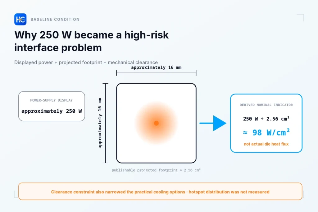
The de-identified heat-source footprint was approximately 16 × 16 mm. The power supply displayed approximately 250 W during the acceptance condition.
Viewed only as total power, 250 W may not appear extreme. Large processors, accelerators, power-electronic devices, and test loads can operate at or above that level.
A 16 × 16 mm projected area is approximately 2.56 cm². Dividing the displayed power by that projected area gives:
250 W ÷ 2.56 cm² ≈ 98 W/cm²
This is a nominal projected-area power density, not the actual die heat flux.
It does not reveal the die area, hotspot distribution, package spreading resistance, or whether heat reaches the cooling interface uniformly. It is a warning flag calculated from the publishable footprint and displayed power—not a complete heat-flux map.
Even with that limitation, the calculation explains why a seemingly moderate total wattage could still create a difficult interface problem. When heat is concentrated into a small contact area, the result becomes more sensitive to the thermal path near the source: package structure, contact condition, TIM, clamping, spreading, and cooling-interface geometry.
The system also had limited vertical clearance above the heat source. A very large tower-style air cooler was not mechanically practical.
Liquid cooling was therefore not selected because 250 W always requires liquid cooling. The combination of footprint, nominal power density, interface conditions, and mechanical clearance made a commercially available liquid-cooling solution a practical baseline option.
Why the off-the-shelf solution came before a custom cold plate
The objective was not to identify the best commercial product.
The product name and model are intentionally omitted because the result belonged to one assembly, one set of displayed conditions, and one acceptance method. Publishing the model could encourage readers to treat the article as a product ranking or universal endorsement.
The actual question was narrower:
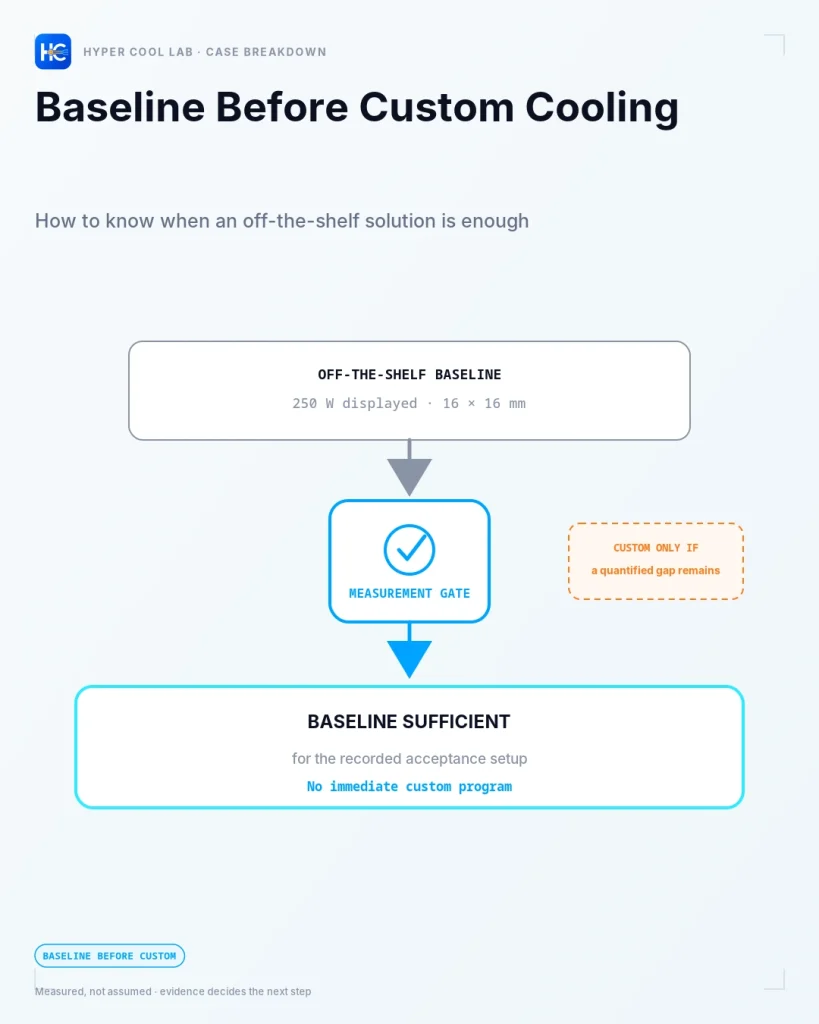
Could a commercially available, non-custom liquid-cooling solution pass the project’s recorded temperature criterion?
Testing the standard solution first created a lower-complexity reference.
If it passed, the team could avoid unnecessary custom non-recurring engineering work.
If it failed, the result could begin defining the gap. A useful custom target requires more than saying that the current setup is too hot. The team would need to know:
- how far the result missed the requirement;
- whether the result was repeatable;
- whether temperature responded to flow;
- whether the bottleneck was in the cooling component, TIM, clamping, or heat source;
- what pressure-drop or mechanical constraints applied;
- and what measurable improvement would justify custom development.
Without a baseline, custom design begins with an assumption. With a baseline, it begins with a recorded reference.
When Tj cannot be measured directly, define a measurable acceptance point
The original requirement was expressed in terms of junction temperature, or Tj.
That was the temperature the product team ultimately cared about, but Tj could not be measured directly in this acceptance setup.
The customer therefore used package thermal data and its internal engineering criteria to define a measurable case-side acceptance limit. This conversion was package-specific. It was not a universal Tj-to-Tcase rule.
The setup used a heater emulator. It reproduced the de-identified projected footprint and applied heat condition needed for this acceptance process.
It did not reproduce the complete internal thermal path of the actual semiconductor package. It should not be interpreted as a full model of the die, package materials, internal spreading, or hotspot distribution.
At the center of the heater emulator was a raised, flexible measurement point containing a temperature sensor. That location corresponded to the case-side point defined for the project’s acceptance method.
In this article, it is called:
the Tc-corresponding acceptance point defined for this case
For readability, later sections refer to it as the Tc-corresponding point. It was not a direct Tj measurement, and it was not a standardized Tcase definition that can be transferred to another package.
The recorded acceptance setup
The evidence source is part of the condition
| Item | Recorded condition | Evidence source |
|---|---|---|
| Applied power condition | Approximately 250 W | POWER-SUPPLY DISPLAY |
| Coolant condition | 20°C | CHILLER DISPLAY |
| Flow condition | 2 L/min | CHILLER DISPLAY |
| Tc-corresponding point | 63°C | RECORDED AT ACCEPTANCE POINT |
| Primary stability rule | <0.2°C / 3 min | Recorded acceptance procedure |
The recorded setup passed the prototype gate
The Tc-corresponding point recorded 63°C, below the 70°C threshold under the recorded setup.
The same record did not characterize the cooling component
Pressure drop, independent DUT-inlet conditions, endpoint power, repeatability, remount reproducibility, and uncertainty were not established.
| Item | Recorded condition | Evidence source |
|---|---|---|
| Applied power condition | Approximately 250 W | Power-supply display |
| Projected heat-source footprint | Approximately 16 × 16 mm | De-identified case geometry |
| Cooling solution | Commercially available, non-custom liquid-cooling solution | Recorded assembly |
| Coolant condition | 20°C | Chiller display |
| Flow condition | 2 L/min | Chiller display |
| TIM | Indium foil | Recorded assembly |
| Clamping control | Total force checked with a load cell | Recorded procedure; numerical value not disclosed |
| Acceptance threshold | Tc-corresponding point ≤70°C | Customer-defined criterion |
| Recorded temperature | 63°C | Temperature sensor at the Tc-corresponding point |
| Primary temperature-stability rule | Less than 0.2°C change over three consecutive minutes | Recorded acceptance procedure |
The evidence-source column matters.
The 63°C value came from the temperature sensor at the case-defined acceptance point. The approximately 250 W power condition came from the power-supply display. The 20°C and 2 L/min conditions came from the chiller display.
They did not all come from an independent, calibrated, synchronized measurement chain.
What the evidence could—and could not—support
The case contained three evidence states.
| Evidence state | Items in this case | Appropriate use |
|---|---|---|
| Recorded at the acceptance point | 63°C at the Tc-corresponding point | Determine whether the case-defined temperature criterion passed |
| Equipment-displayed conditions | Approximately 250 W, 20°C, and 2 L/min | Document the original operating setup at the available evidence level |
| Not measured or not formally studied | DUT-inlet temperature, independent flow, pressure drop, endpoint power, repeatability, remount reproducibility, uncertainty | No characterization, supplier ranking, or production-level conclusion |
This does not make the acceptance record invalid.
It means the conclusion must remain proportional to the evidence.
The record supports:
The off-the-shelf solution passed the recorded Tc-corresponding acceptance criterion.
It does not support:
- a calibrated cold-plate thermal resistance;
- a verified 2 L/min DUT flow at exactly 20°C;
- universal performance at 250 W;
- production qualification;
- certification;
- or long-term reliability.
TIM and clamping were part of the baseline
The acceptance sequence used indium foil as the thermal interface material.
The same indium foil was used throughout the relevant acceptance sequence, and total clamping force was checked with a load cell. The numerical force value is not disclosed.
The purpose was to reduce assembly variation—not to recommend indium as a universal TIM.
Mounting is part of the measured thermal path. If TIM condition, clamping force, flatness, or contact state changes, a temperature difference may come from the interface rather than the cooling solution.
A load cell confirms total applied force. It does not prove uniform pressure distribution, surface parallelism, or complete local conformity.
Similarly, using the same indium foil in this sequence does not establish that all indium foils can be reused indefinitely under every pressure, surface, or cycling condition.
The narrower conclusion is:
Key interface conditions were recorded and constrained for the original acceptance sequence.
This is why a baseline is more than a product test. The temperature result belongs to the complete recorded assembly, not to the cold plate alone.
A temperature-stability rule is not a full boundary-control definition
The primary temperature-stability rule was:
The Tc-corresponding reading had to change by less than 0.2°C over three consecutive minutes.
This was more explicit than visually judging whether a curve appeared flat. It defined a numerical change and a time window.
However, it was not a complete multi-variable steady-state definition.
The original process did not independently and synchronously record DUT-inlet coolant temperature, actual flow, and endpoint electrical power during that same three-minute window.
The chiller and power-supply displays provided the available operating references. They did not form a full characterization-grade measurement chain.
The correct interpretation is therefore:
The primary temperature reading was stable enough to satisfy the original acceptance procedure.
A characterization program would normally define simultaneous acceptance bands for the primary temperature, coolant inlet temperature, actual flow, electrical power, and—in a contact-sensitive setup—clamping condition.
The difference is not that one process is real and the other is not.
The difference is the strength of the conclusion each process can support.
What this result was strong enough to decide
The Tc-corresponding point recorded 63°C. The agreed threshold was 70°C.
The recorded value was 7°C below the threshold.
That observation should not automatically be called a 7°C design margin. A formal margin would need to account for measurement uncertainty, boundary-condition variation, mounting reproducibility, workload variation, and project-specific allowances.
But the result answered the immediate acceptance question.
Under the recorded setup:
- the power supply displayed approximately 250 W;
- the chiller displayed 20°C and 2 L/min;
- the recorded indium interface and clamping procedure were used;
- the Tc-corresponding temperature satisfied the three-minute stability rule;
- and the reading was below the agreed threshold.
The decision was:
Baseline sufficient for the recorded acceptance setup.
In practical terms, the off-the-shelf solution passed the prototype gate. This result alone did not justify an immediate custom cold-plate program.
That is a legitimate engineering outcome.
Avoiding unnecessary custom development can preserve budget, shorten the dependency chain, and keep the architecture simpler until stronger evidence shows that additional complexity is needed.
What this result was not strong enough to establish
The same record did not complete thermal characterization.
It did not establish:
- calibrated thermal resistance of the cooling component;
- pressure-drop behavior;
- flow-versus-temperature response;
- sensitivity to coolant inlet temperature;
- same-mount repeatability;
- remount reproducibility;
- measurement uncertainty;
- production assembly variation;
- transient behavior;
- or reliability under aging and environmental change.
These gaps do not reverse the acceptance result. They define its boundary.
Supported conclusion
The recorded setup passed the case-defined prototype temperature criterion.
Unsupported conclusions
The result does not characterize the cooling component, certify the assembly, rank suppliers, or establish production reliability.
A narrow result remains useful when its scope is explicit.
Why 0.172°C/W is not the cold plate’s thermal resistance
(63°C − 20°C) ÷ 250 W≈ 0.172°C/WThe recorded values can be combined:
(63°C − 20°C) ÷ 250 W ≈ 0.172°C/W
The calculation is arithmetically correct.
It is not a calibrated cold-plate thermal resistance.
The temperature difference uses the Tc-corresponding sensor reading and the chiller-displayed temperature. The denominator uses power-supply-displayed power. The complete path includes the heater emulator, sensing location, indium interface, contact condition, cooling assembly, and displayed boundary values.
The result is therefore best described as:
a nominal temperature-difference-to-displayed-power ratio for the recorded setup
It may be useful as a reference if the same setup and definitions are repeated. It should not be transferred as a component specification.
Calculated does not automatically mean characterized.
If the baseline had failed, custom cooling still would not be the first conclusion
Suppose the recorded temperature had exceeded 70°C.
That would show that the recorded setup failed the acceptance criterion. It would not, by itself, prove that the commercial cooling component lacked sufficient capacity.
The result could also be affected by:
- TIM condition;
- bond-line thickness;
- clamping or flatness;
- lower-than-expected actual flow;
- higher-than-expected inlet temperature;
- sensor placement or interpretation;
- the heater emulator’s internal path;
- or the relationship between the acceptance point and the real device.
Each possibility leads to a different next step.
If the interface is the main limitation, designing a new cold plate may mask the problem rather than resolve it.
If the internal device path dominates, improving the external coolant path may deliver limited benefit.
If the hydraulic boundary is not what the display suggests, redesigning before verifying actual flow may lead to the wrong geometry.
A failed baseline should trigger diagnosis—not an automatic custom-design order.
Decision record
Decision question
Could a commercially available, non-custom liquid-cooling solution pass the agreed prototype temperature criterion?
Recorded setup
- Approximately 250 W shown by the power supply
- Approximately 16 × 16 mm projected footprint
- 20°C and 2 L/min shown by the chiller
- Heater emulator with a central Tc-corresponding temperature sensor
- Indium foil interface
- Total clamping force checked with a load cell
- Primary temperature-stability rule of less than 0.2°C change over three minutes
Acceptance result
- Threshold: Tc-corresponding point ≤70°C
- Recorded value: 63°C
Decision
Baseline sufficient for the recorded acceptance setup.
What this supports
- The off-the-shelf solution passed the defined prototype gate.
- Immediate custom-cooling investment was not justified by this result alone.
What this does not support
- Calibrated component characterization
- Universal 250 W capability
- Supplier ranking
- Certification
- Production or reliability sign-off
- Performance outside the recorded setup
This is the difference between leaving behind a temperature reading and leaving behind an engineering decision.
What evidence would actually justify custom cooling?
Custom cooling becomes technically justified when the baseline reveals a quantified and sufficiently credible gap.
Several conditions usually need to be met.
First, the standard solution must fail a defined requirement under boundaries that are adequate for the decision.
Second, alternative causes should be investigated. Contact, TIM, clamping, flow, inlet condition, sensing, and internal heat spreading should not remain obvious uncontrolled explanations.
Third, the gap should be measurable. The team should know how far the baseline misses the target and under which conditions.
Fourth, the custom target should be explicit. It might require:
- a defined reduction in case-side temperature;
- a higher allowable coolant inlet temperature;
- a lower-flow operating point;
- a pressure-drop limit;
- a smaller mechanical envelope;
- or improved assembly repeatability.
Finally, the expected improvement should justify the added complexity. Custom cooling can introduce machining constraints, sealing risk, cleaning requirements, tolerance control, supplier qualification, and maintenance dependencies.
Custom cooling should not be the default response to thermal uncertainty.
It should be the result of a recorded technical gap that a custom design is specifically intended to close.
- The standard solution fails a defined requirement under boundaries adequate for the decision.
- Contact, TIM, clamping, flow, inlet condition, sensing, and internal spreading have been investigated.
- The performance gap is quantified and tied to explicit operating conditions.
- The custom target specifies the required improvement, not merely “more cooling.”
- The expected gain justifies machining, sealing, pressure-drop, tolerance, and supply-chain complexity.
The value of a baseline is a smaller, better-defined next step
This case did not end with a custom cold plate.
That was not a lack of progress.
The off-the-shelf solution passed the defined prototype criterion under the recorded setup. The result prevented the team from committing engineering time and budget to custom development before the evidence required it.
A baseline can produce several valid outcomes:
- Baseline sufficient: the current solution passes the defined decision gate.
- Mounting or interface issue: the cooling component may not be the main problem.
- Data insufficient: the available record cannot yet support the decision.
- Custom justified: the standard solution shows a quantified gap after relevant alternatives are addressed.
All four outcomes reduce uncertainty.
The evidence burden should match the risk and irreversibility of the next decision. A prototype acceptance process does not need to imitate a full qualification program. But it must not be described as though it were one.
The central principle is:
Use the least complex evidence set that can answer the actual decision—and state clearly what it cannot answer.
That is how a baseline turns thermal testing into an accountable engineering decision rather than a collection of temperatures.
Is your current cooling solution ready for a baseline test?
Before committing to custom cooling, organize the conditions that define the decision:
- heat-source or package dimensions;
- power conditions and whether each value is a setpoint, equipment display, estimate, or independent measurement;
- measurable temperature location and acceptance target;
- coolant, airflow, or environmental boundaries;
- TIM and mounting conditions;
- the current cooling solution;
- mechanical constraints;
- and the design, tooling, or prototype commitment being considered.
Hyper Cool Lab uses the initial information to assess fit, identify material evidence gaps, and define an appropriate validation scope.
The initial scoping step does not provide a free cooling architecture, an untested wattage claim, certification, or production sign-off.
Organize the inputs → assess fit and evidence gaps → define a scoped validation path
How Hyper Cool Lab approaches this type of question
Hyper Cool Lab is a thermal validation and ground-truth lab for high-power hardware prototypes. It uses controlled measurements, baseline comparisons, and accountable engineering interpretation to support decisions before irreversible design, tooling, or custom-cooling commitments.
A validation scope may determine whether additional measurement, characterization, or custom development is justified under stated conditions. It does not guarantee lower temperature, certify untested conditions, or assume responsibility for final product qualification.
Frequently asked questions
Does 250 W always require liquid cooling?
No. Total wattage alone does not determine the cooling architecture. Heat-source area, local heat concentration, available space, temperature limits, airflow, contact conditions, and the complete thermal path also matter.
Can a Tc-corresponding measurement replace Tj?
Only within a package-specific acceptance method supported by appropriate thermal data. The point used in this case was not a direct junction-temperature measurement and should not be transferred to another package.
Was the 2 L/min flow independently measured?
No. It was the value shown on the chiller display. It documented the original setup but did not provide calibrated flow characterization at the device under test.
Is 0.172°C/W the cold plate’s thermal resistance?
No. It is a nominal ratio based on the Tc-corresponding reading, chiller-displayed temperature, and power-supply-displayed power. It represents the recorded setup, not the cooling component alone.
Is one passing result enough for production use?
No. One result may close a prototype acceptance gate. Production or reliability sign-off requires evidence covering the intended conditions, variation, environment, aging, uncertainty, and qualification responsibility.